
Welcome to the fourth Max Gen! This will be the final tutorial looking at delays in Max’s Gen, from Cycling ’74. Today we’ll show you a cool function on the delay object inside Gen.
You can have multiple taps (delay lines) within one [delay] object: with two delay lines, you can update one of them and crossfade to the other. This gives different sounds from tape style delays. We’ll be using this to make today’s delay patch.
Test the patch here: XFadeDelay
1.) We’ll build on our patch from Tutorial 3. You can download this and the TXDelay patch we’ll be drawing on from our Github:
https://github.com/pingdynasty/OwlGenPatches
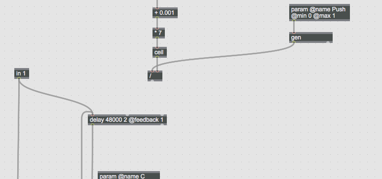
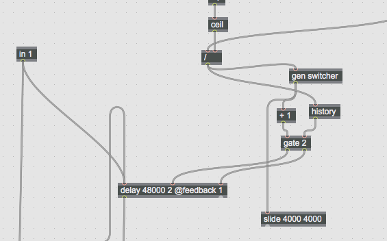
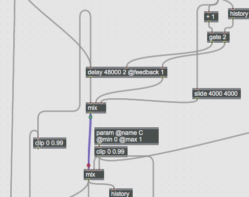
Let’s begin by getting rid of and move things around to give us more space. Now let’s add an extra delay line. To do this we add a second argument to [delay]. This argument specifies the number of delay lines, so we update it to 2, giving us [delay 48000 2 @feedback 1].
You’ll notice an extra inlet and an extra outlet appear. The second inlet is the delay time for the first delay line, the third inlet is the delay time for the second delay line (and the first inlet is still the signal that is to be delayed). The first outlet is for the output of the first delay line, the second outlet for the output of the second delay line.
2.) Like we did last time, we’re going to take a few objects from another patch. Open the TXDelay patch. You can get this from github.com/pingdynasty/OwlGenPatches
We’ll copy a bundle of objects consisting of [gen switcher], [+ 1], [history], [gate 2] and .
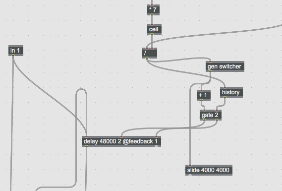
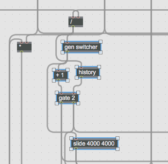 3.) We can now paste these objects into our [gen~] patch, and connect the delay time (the output from [/]) into both [gen switcher] and [history], and the two outputs from [gate] into inlets 2 and 3 of [delay].
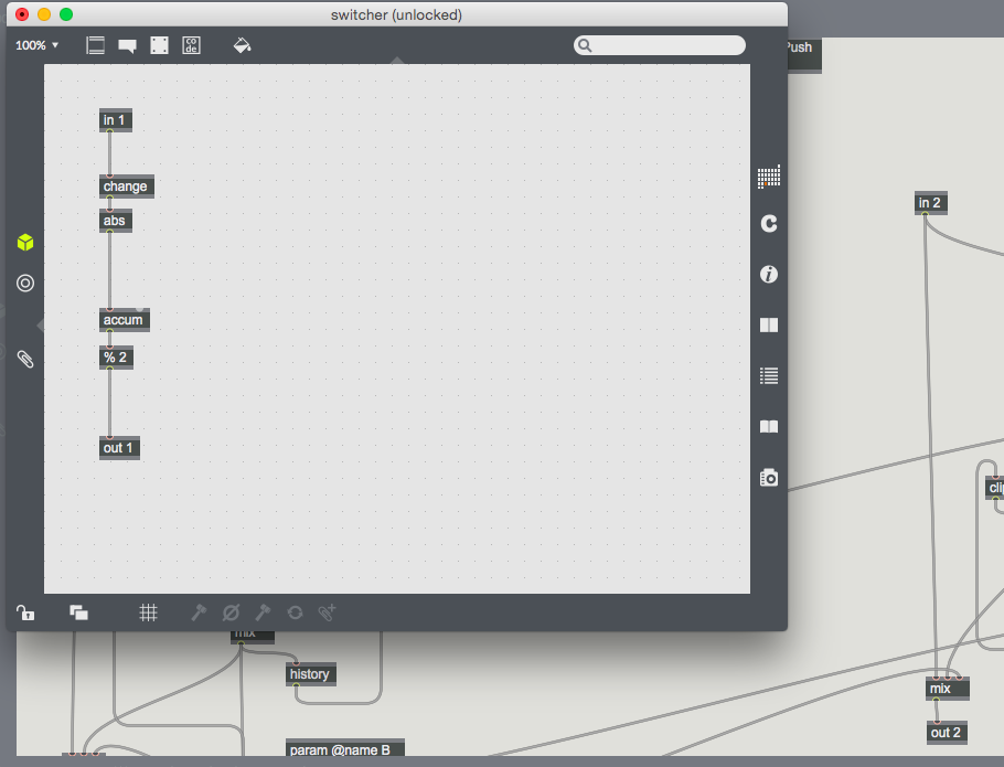
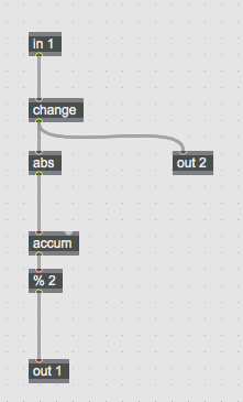
 4.) The key thing is clearly [gen switcher], so let’s open it up. First of all, you can see a new object called [change]. This is a bit different to the max object [change] which (as you may know) only passes a value when there’s a change. Gen’s [change] returns the sign of the difference. This means every time there is a change in the positive direction (ie if the value goes up) it spits out a 1, and if it goes down it spits out a -1, and if it stays the same it spits out a 0.
Because the values will end up in [accum], we want to keep the output as a boolean, a simple 0 or 1, so when there’s a change there’s a 1, and when there’s no change it spits out 0. We use [abs] which gives the absolute value of what’s coming in, so this changes -1 to 1. [accum] counts what’s coming in and outputs the count which goes into [%], the modulo. For every value, [% 2] will alternate between 1 and 2.
5.) To demonstrate how these objects are working, we can create an [out 2] in [gen switcher] and an [out 3] in our gendsp patch, then in the main maxpat and create a [scope]. We can see, if we connect the output of [change] to [out 1], the new second output of [gen switcher] to [out 3], and the new output of our [gen~] object to a [scope~], that every time we increase the value we get a 1 and every time we decrease the value we get -1. We can connect different objects within [gen switcher] to the [out 2] in [gen switcher] to see their behaviour. Looking at the output from [abs], we can see that we add 1 every time we change delay value. Looking at the output of [accum] in a [number~], we can see it counts every time the delay time is updated.
6.) We only have two delay lines we are switching between, so we only need two values to be outputted from [gen switcher]. This value will tell us which delay line we are working with. Since the output is going into the selector input on [gate] and this only has two outputs, we need the values 1 and 2. This is where [%] (modulo) comes in handy. It alternates the output between 0 and 1. Now, every time we change the value for the dial a, [gen switcher] outputs 0 or 1. The [+ 1] adds one to this, giving the [gate] path selector input the 1 or 2 it needs.
7.) We are alternating the delay time, and the outputs from [gate] are going into the two delay lines. We need a particular order for the logic here, which is why we’ve used the [history] object. Before the new delay value comes to the [gate], we want the correct path to be open for the new value to go to. [history] delays the delay time value by 1 sample. This means that upon changing delay, first the gate opens through to the new path, and then the delay value arrives and is sent down this path. Now, every time you change the delay time, it goes into the new tap and the new tap will update the value immediately.
8.) Now we need another [mix] object. The output of [gen switcher] goes through a object and into the third inlet of this [mix], the interpolation factor between the two inputs.
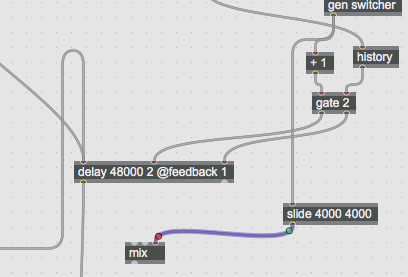 9.) The two outputs from [delay] go into the first two inlets for [mix], and this connects to the other [mix] object that was already in our patch. We now automatically crossfade between the delay lines every time we change the delay time.
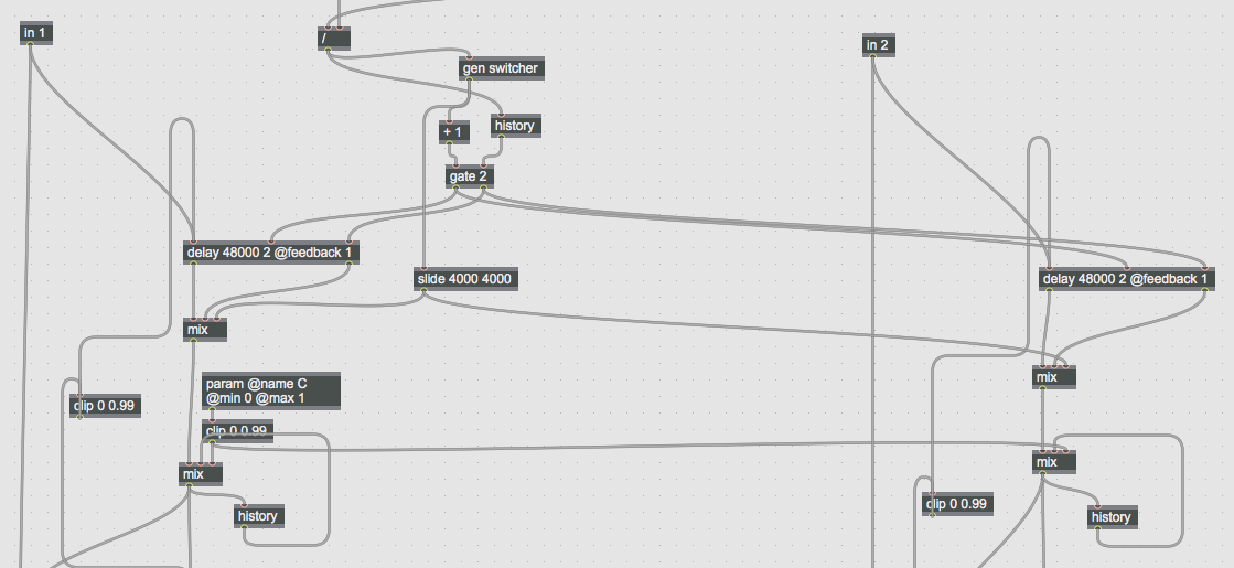
10.) We can set this up for the second channel. If we test this finished patch in our Max patch we can hear there is no pitch change when changing delay times!
 So, now you’ve made a great sounding delay! Upload this patch to the OWL using the online compiler at www.rebeltech.org.
Even if you don’t have an OWL, you can test the delay in the browser.
You can find more instructions about compiling Gen patches for the OWL at http://www.rebeltech.org/2016/11/owl-max-tutorial-1-getting-started/